Network equipments
Network equipment represent the hardware that manages, transmits and route network between several other equipments (computers, printers…).
A network equipment can be a switch, an Ethernet hub, a router, a firewall or a WiFi access point.
It is possible to use templates with network equipments.
Astuce
Note that if you modify a field manually, it will be considered locked. This will prevent it from being modified the next time the automatic inventory is uploaded.
For more information, see lock
Network device
Network device tab, includes basic information about the material :
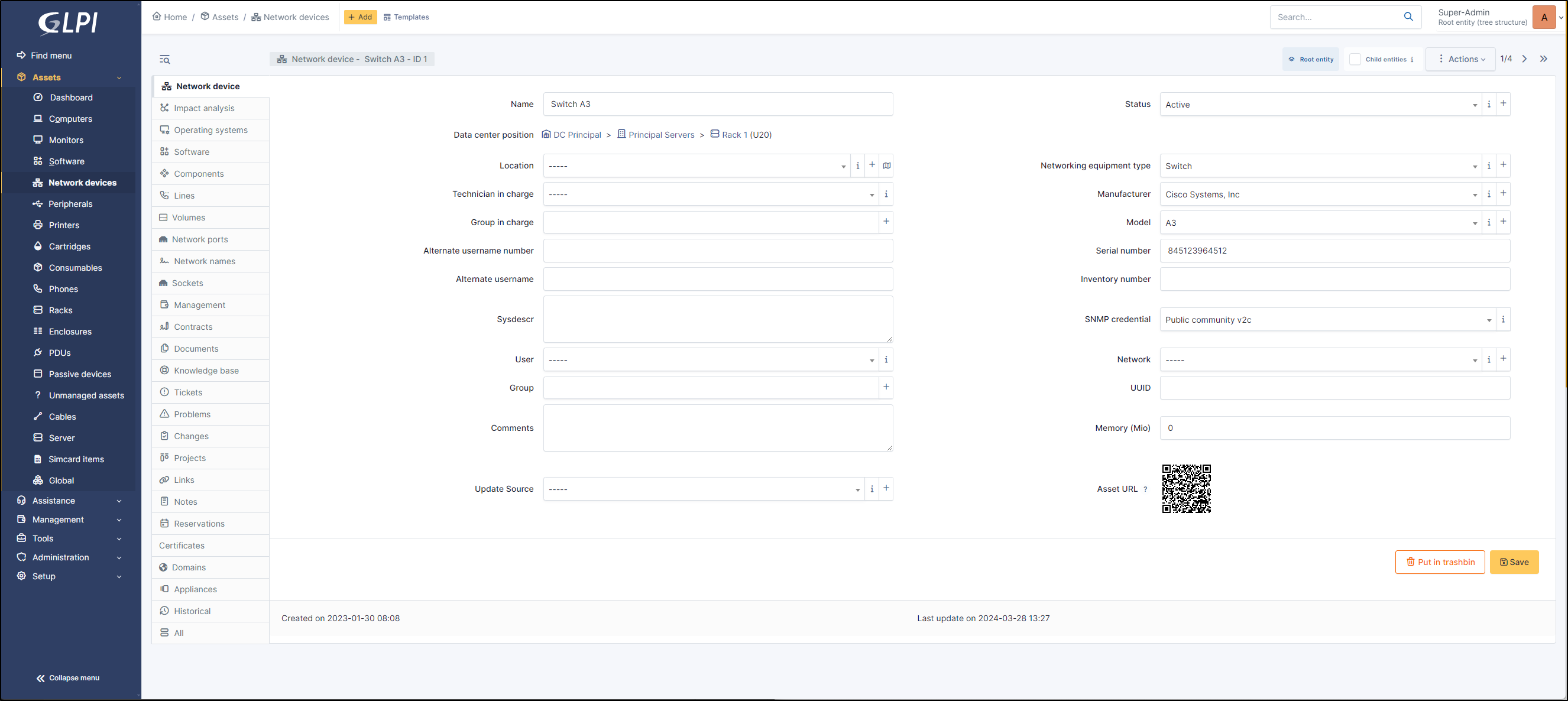
Name
If your computer has been inventoried by the automatic inventory, you can find information about the GLPI Agent
Agents
Public contact address
Agents Status
Useragent
Last contact
Request inventory
Inventory tag
Last inventory update
Impact Analysis
Impact analysis enables an infrastructure diagram to be drawn up, showing the dependencies and impacts in the event of equipment loss. This can be saved and exported
Operating systems
Operating systems includes information about your machine’s OS :
Name
Version
Architecture
Service Pack
Kernel
Edition
Product ID
Serial number
Company
Owner
Host ID
Installation date
Software
Lists all the software brought up during the inventory and those added manually
It is possible to install (in the logical sense) software on a device manually.
To add new software to the list of applications, you need to go to the Assets > Software tab, which will then be visible from the software tab of the various elements of the installed base.
Components
This tab lists the PC’s components :
BIOS
Processor
Memory
Hard Drive
Network card
Drive
Battery
Graphics card
Soundcard
Controller
Each item has its own information (name, model, brand, memory capacity, number of cores/threads, etc.).
Lines
You can add telephone lines created in Lines
Volumes
Summarises all the volumes present (hard disk, DVD) as well as the partitions present on the workstation (virtual disks such as Google Cloud may appear if they are installed as a network drive).
Name
Automatic inventory (Yes /No)
partition
Mount point
File system
Global size
Free size
Free percentage
Encryption (if the disk is encrypted, a padlock will be displayed)
Network Ports
This tab allows to manage the network ports attached to an equipment. The information that can be viewed is:
Name
Port number
MTU
Speed
Internal status
Last change
Number of I/O bytes
Number of I/O errors
Duplex
VLAN
Connected to
Connection
Deleted
Network Name
Network names are used to organise and identify network devices in a more structured way. They usually appear as a dropdown list and are useful for defining specific network categories or contexts.
The visible fields are :
Network name
IP addresses
IP networks
Sockets
Sockets are the list of physical sockets present on the hardware. These sockets can be Ethernet, USB, HDMI, etc. This information cannot be returned by the automatic inventory, so you have to add it manually.
It enables hardware to be linked by cables. Socket is also linked to the cables object
Management
Management of financial and administrative information, this information is visible in the “Management” tab on the computer’s form.
Contracts
GLPI supports contracts management, in order to manage contract types such as loan, maintenance, support…
Contracts management allows to:
make an inventory of all contracts related to the organization assets
integrate contracts in GLPI financial management
anticipate and follow contract renewal.
Documents
The document tab lets you link different types of file to a material (PDF, txt, png, etc.) You can attach a document already uploaded to GLPI or add a new one directly from this tab.
Knowledge Base
Lists all the articles in the knowledge base relating to the material.
Tickets
View all tickets linked to the computer
Problems
This tab refers to all hardware-related problems. Problems can also be linked to tickets, projects, etc. This allows you to have a complete scenario when necessary.
Changes
Changes lists all changes related to a material. From this tab, you can’t link a change directly, you can do it from Assistance > Changes > Items. You can create a new change from this page, which will be linked to the material you have selected.
Projects
This tab lists all the projects linked to the software. Here you can only add a project that already exists. To create a new one, go to Projects
Links
Links offer several possibilities. Send the GLPI object file to another URL of your choice, or generate an RDP file, for example.
Notes
Note lets you add enriched text and attach a document.
Reservations
The reservation tab lets you reserve equipment, view the reservation schedule, or cancel the possibility of reserving this equipment. By default, equipment cannot be reserved; you must first authorize this action manually.
Certificates
Link a certificate to your registration. You can manage certificates in Management > Certificates
Locks
Locks are used to prevent a field from being modified when the inventory is uploaded. You can lock/unlock the fields you wish in a GLPI object.
Notes
Note lets you add enriched text and attach a document.
Reservations
The reservation tab lets you reserve equipment, view the reservation schedule, or cancel the possibility of reserving this equipment. By default, equipment cannot be reserved; you must first authorize this action manually.
Domains
You can attach Domains to your computer. Domains are also linked to other objects such as records, problems, etc.
Appliances
Appliances includes all business applications managed within GLPI. They can be linked to another GLPI object (computer, application, etc.) as well as to another appliance.
Databases
Databases list databases discovered by automatic inventory and those entered manually
Import information
Import information is information that is uploaded and governed by equipment import rules (administration > rules > Rules for import and link equipments)
History
The History tab is used to show any changes made to an item. The following information about the changes is available:
ID of the change.
Date and time the change was made.
User who made the change. If this field is not filled, it means that the action was done automatically (For example: automatic inventory update).
Field that was changed.
Description of the change that was made.
The description of the change represents either the difference between the old and the new value (For example with location field: Change HQ to Remote Office A), or the explanation of the action which was carried out (For example: Uninstallation of a software: « Gimp 2.0 »).
Note
For dropdowns or objects with a parent/child relationship, the modification of a child will appear in the history of the parent element.
All Information
For an item, all information is displayed on one page from the All tab. This shows all of the tabs of an object’s form in one view, one below the other.
The different actions
Network equipments do not have specific actions; report to common actions.